Hardware and operating systems · part 3 of 3
Cache: lines, associativity and what happens on a miss
How a cache finds data by tag, index and offset, what happens on a miss, and how associativity and replacement change the hit rate.
intermediatePublished on · 39 min read
Picture the front shelf of a market. It sits at hand height, keeps only what sells fast, and when a product runs out, the clerk goes to the storeroom and brings back a whole box, not a single unit. A cache works in much the same way. It is a small memory made of SRAM, placed between the CPU and RAM, that keeps copies of data used recently or likely to be used soon. When the CPU asks for data that is there, the answer comes back in a few cycles. When it is not there, that is a miss, and the data has to come from a slower level.
Lesson Memory hierarchy and locality showed why there are several levels and why locality makes the cache work. This lesson goes into the L1 level and asks how it does its job: how it finds data without scanning everything, what it stores next to each piece of data, who leaves when space runs out, and what happens when the CPU writes. The physics of the cells that make up the cache is covered in SRAM, DRAM and storage and is not repeated here.
Lesson map
| Section | Question it answers |
|---|---|
| 1. What a cache is and why it stores lines | Why doesn’t the cache copy one byte at a time? |
| 2. What it is for | What design problem does the cache have to solve? |
| 3. Examples in different contexts | Where does the same logic appear outside the CPU? |
| 4. How it works inside | How does an address become tag, index and offset, and what happens on a hit and on a miss? |
| 5. Details and edge cases | What does associativity cost, and how does it interact with the locality from lesson 4.1? |
| 6. Common mistakes and good practices | Which code decisions depend on the cache? |
| 7. Simulation and measurement | How many misses does each organization cause on a known access pattern? |
| 8. Exercises | Calculation and design questions, with reference answers |
| 9. Glossary | Technical terms used in this lesson |
| What was not confirmed | Which numbers and claims are a model, and not a measurement or a primary source? |
| Sources | Where the facts come from, and when they were checked |
1. What a cache is and why it stores lines
The reference CPU for this track answers in 4 cycles when the data is in L1. RAM takes about 496 cycles to answer. Having fast memory close to the core is great, but it only helps if it keeps what the CPU is going to ask for next, and that depends on the program having good locality.
Notice something most people do not expect. The cache does not store loose bytes. When the CPU asks for a single byte that is not in L1, the hardware brings in a whole block of bytes, aligned to a multiple of the block size. That block is the cache line, and in this lesson’s reference it is 64 bytes. The line is the unit of transfer between RAM and the cache. Nobody buys a single egg from the farm. You buy the carton. The cache works the same way: the trip to RAM is already expensive, so bringing the neighbors along usually pays off, as long as the program uses them.
Besides the 64 bytes of data, each line stores some control information: whether the line is in use, whether it was changed, and which RAM block it came from. Section 4 shows each of them. For now, it is enough to know that the unit of the cache is the line, not the byte.
2. What it is for
Imagine a cache with no search method at all. To know whether an address is stored, the CPU would have to compare it with each of the 512 lines of the 32 KB L1. Doing 512 comparisons in 4 cycles does not fit in hardware. The cache has to answer with a direct calculation that says where to look, and then with only a few comparisons in that place.
That requirement forces the design to answer four questions. The first is where a block may live, and the answer defines the organization of the cache: direct mapped, set associative or fully associative. The second is how to find the block, and the answer is splitting the address into tag, index and offset. Each of these fields is a group of bits of the address: the tag identifies the block, the index picks the set, and the offset picks the byte. Section 4.1 explains all three with the full calculation. The third is who leaves when space runs out, which is the replacement policy. The fourth is what to do when the CPU writes, which is the write policy. Each answer has a cost in area, energy and time, and none of them is free. Section 4 goes through all four, starting with the organization, which changes the hardware the most.
3. Examples in different contexts
The same logic appears in structures that have nothing to do with hardware.
The first example is a fixed-size hash table with 64 buckets and room for two items in each bucket. The hash function picks the bucket, which plays the role of the index. Inside the bucket, the search compares keys, and those keys play the role of tags. When the bucket fills up, one item has to leave to make room for the new one. This is the closest image of a set-associative cache, and it works as a mental model, not as a description of the hardware.
The second example is a parking lot. If each license plate has a fixed space, two cars with the same space compete for it, and the second one cannot enter while the first is there, even if the whole lot is empty. That is direct mapping. If the space is chosen among the spaces in the same row, the competition only happens within that row. If any space will do, a car is only turned away when the lot is full.
The third example comes straight from lesson 4.1. An integer vector of 4-byte values, read from start to end, causes a miss every 16 reads, because the 64-byte line brings 16 integers at once. That 6.25% rate shows up in section 7 even when the vector is larger than the cache, because spatial locality keeps the pattern going. What changes between the examples is the choice rule. The arithmetic behind each one is the same: how many slots exist, and how many things compete for each slot.
4. How it works inside
4.1 Splitting the address into tag, index and offset
When the core calculates an address, the cache treats its bits as three fields. The offset is the group of least significant bits, which picks the byte inside the line. With 64-byte lines, that is 6 bits, because 2 to the power of 6 is 64. The index is the group of bits right above the offset, and it picks the set of lines where the block may be. The tag is the group of bits left at the top, and it says which RAM block sits in that line.
In the reference L1, which is 32 KB with 8 ways and 64-byte lines, there are 32 KB divided by 64 bytes, which means 512 lines. Since each set has 8 ways, that is 512 divided by 8, or 64 sets. So the index has 6 bits, because 2 to the power of 6 is 64. In a 32-bit address, the tag gets what is left: 32 minus 6 for the offset and minus 6 for the index, which gives 20 bits.
The figure shows the 32 bits of address 0x12345678, colored by the field each bit belongs to.
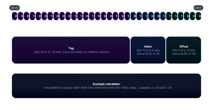
Read the figure from left to right. The 20 tag bits form 0x12345. The 6 index bits are 011001, which is 25 in decimal. The 6 offset bits are 111000, which is 56. This address therefore looks in set 25 for byte 56 of the line. If any way in that set is valid and has tag 0x12345, we have a hit. Otherwise, we have a miss.
Notice that the index only decides where to look. It does not identify the block. Two addresses with the same index and different tags compete for the same set, and the ones that differ only in the tag are exactly the ones that get in each other’s way. This detail is the key to understanding the conflicts in section 5.
This lesson uses 32-bit addresses so the numbers fit on the page. A real processor has larger physical addresses, and the tag grows with them. With a 48-bit physical address, for example, the same L1 would have a 36-bit tag, by the same arithmetic: 48 minus 6 minus 6. How many physical address bits each processor uses was not confirmed in this lesson.
4.2 The cache line: control bits, tag and data
Each entry in the array stores four things. The V bit (valid) says whether the entry holds real data. When the cache has just been powered on, every entry has V equal to 0, because nothing is stored yet. The D bit (dirty), used only for writes, marks that the line was changed since it came from RAM. The tag identifies the block. The 64 bytes are the actual data.
The figure follows the path of a read of one byte that is not in the line.
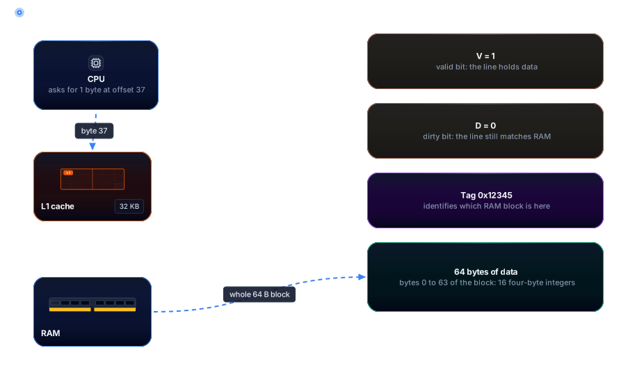
The CPU asks for byte 37, but what comes out of RAM is the whole block, 64 bytes, and it is stored in L1. Since 64 bytes equal 16 four-byte integers, a single transfer serves the next 16 reads of those integers. This is where the spatial locality from lesson 4.1 turns into a concrete gain.
The 64-byte size is not universal, so it is worth saying where the number comes from. On the x86 machines used as reference in this lesson, the line is usually 64 bytes. The secondary source consulted, WikiChip, describes the Zen 4 data L1 with 64-byte lines, but AMD’s own documentation was not read in this check. The Apple M1 Max used in this lesson reports 128 bytes through sysctl (section 7). POWER7 to POWER9 also use 128 bytes, according to the secondary sources cited in lesson 4.1. The number cannot be generalized: the choice depends on the processor, and this lesson did not survey other designs.
Larger lines take better advantage of spatial locality, because each miss brings more neighbors. On the other hand, a miss brings more bytes that may never be used, and each entry in the array gets bigger. The trade-off is the same one lesson 4.1 described in its section on cache lines.
4.3 Direct mapped, set associative and fully associative
The organization answers the question of where a block may live. In a direct-mapped cache, each RAM block has exactly one possible entry, chosen by the index. If two blocks with different tags land on the same entry, each swap throws the other one out. The lookup is cheap, because there is a single comparator, but conflicts are frequent.
In an N-way set-associative cache, the index picks a set, and the block may occupy any of the N ways in that set. The lookup compares the tag with all N ways in parallel, which costs N comparators. The reference L1 has 8 ways, so that means 8 comparators per access.
In a fully associative cache there is a single set, with all the lines. There is no index, and the block can go into any entry. To find data, the tag would have to be compared with every line in the cache. That is why this design only fits small structures.
For the same capacity, the number of lines is the same in all three organizations. What changes is how many sets exist and how many ways each one has. For the 32 KB L1 with 64-byte lines, the arithmetic looks like this:
| Organization | Sets | Ways per set | Comparators per access |
|---|---|---|---|
| Direct mapped | 512 | 1 | 1 |
| 2-way set associative | 256 | 2 | 2 |
| 8-way set associative (the reference L1) | 64 | 8 | 8 |
| Fully associative | 1 | 512 | 512 |
The figure shows a miniature with 4 sets and 2 ways, so it fits on the page. The rule is the same as in the real L1: the index picks the horizontal row, and the two columns are the ways.
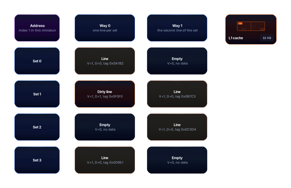
The address from section 4.1 lands in set 1 of this miniature, because 25 divided by 4 leaves remainder 1. That is only a coincidence of the drawing, since the real L1 has 64 sets, not 4. The orange line is dirty, and the dashed lines are empty. Sets 0, 2 and 3 have room, but an address that falls in set 1 can only use its two ways. That limit is what produces the conflicts in section 5.
4.4 Hit and miss walking through the array
A read goes through four steps. The index picks the set. The tag of the address is compared with the tag of each valid way in that set, in parallel. If any way matches and has V equal to 1, we have a hit: the offset picks the byte, and it goes to the CPU. If no way matches, we have a miss.
On a hit, the path is short and does not involve RAM. The figure shows address 0x12345678 looking for set 1 in the miniature.
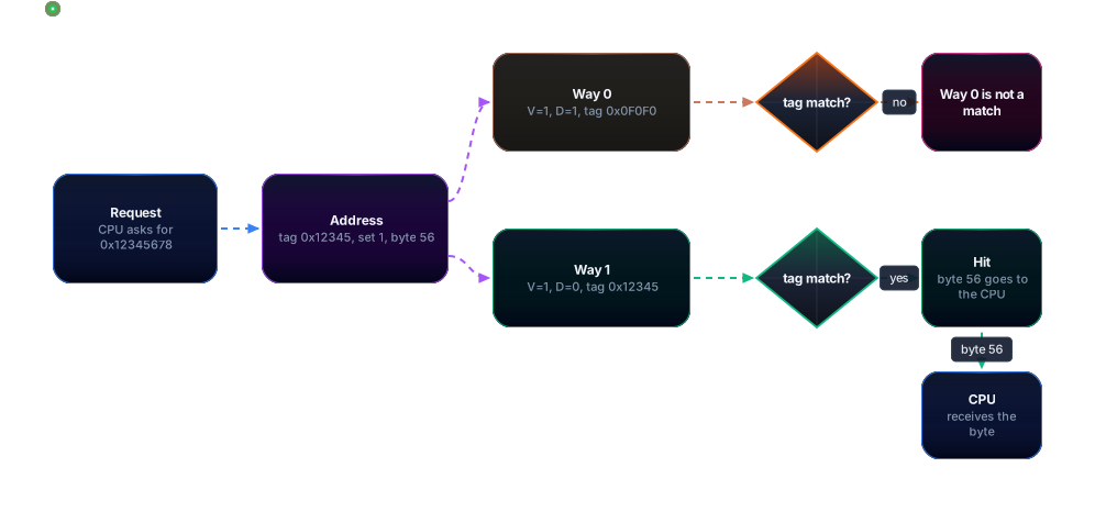
Way 0 has tag 0x0F0F0, which does not match. Its comparator says no. Way 1 has tag 0x12345, which is the address’s tag, and its comparator says yes. That yes is the hit, and byte 56 leaves the line straight for the CPU. The cost is the L1 hit time, which is 4 cycles in the reference.
On a miss, no way matches, and the hardware has to pick a victim among the ways in the set. The choice depends on the replacement policy, which section 4.6 explains. If the victim is dirty, it has to be written to RAM before the new line takes its place. The miss penalty, therefore, can be the trip to RAM plus the eviction of a dirty line, and that is why a miss with a dirty victim costs more than a miss with a clean one. A read in a write-back cache may require two transfers with memory, according to the Wikipedia page cited in the sources.
The next figure follows a miss with a dirty victim.
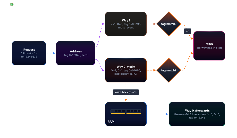
Both comparators say no. Way 0 is the victim, because it is the least recently used, and since D is 1 it writes the whole line to RAM before leaving. Then the new line arrives and occupies way 0 with tag 0x12345, V equal to 1 and D equal to 0. The CPU only receives the byte after that fill. That is why the miss time is the sum of the steps, not just the RAM time.
4.5 The three kinds of miss
Not every miss has the same cause, and separating the causes shows which fix will work. The three Cs model classifies each miss by asking one question at a time.
The first question is whether the block has appeared before in the execution. If it never has, the miss is compulsory, also called a first-reference miss. No organization avoids this miss, because nobody could have stored data that was never read. Only prefetching or larger lines reduce this kind.
If the block has appeared before, the second question is whether a fully associative cache of the same size would also miss. If it would, the miss is a capacity miss: the set of data the program uses is larger than the cache, and the block left because space ran out. Raising associativity does not solve this case. Only more capacity does.
If the fully associative cache would hit, the miss is a conflict miss. The real cache had enough room in total, but the block fell into a full set. This is the kind that associativity fights, and it is the one section 7 measures.
The definition is operational. The simulator in section 7 does exactly this comparison, with a fully associative reference of the same size. The figure puts the three cases side by side.
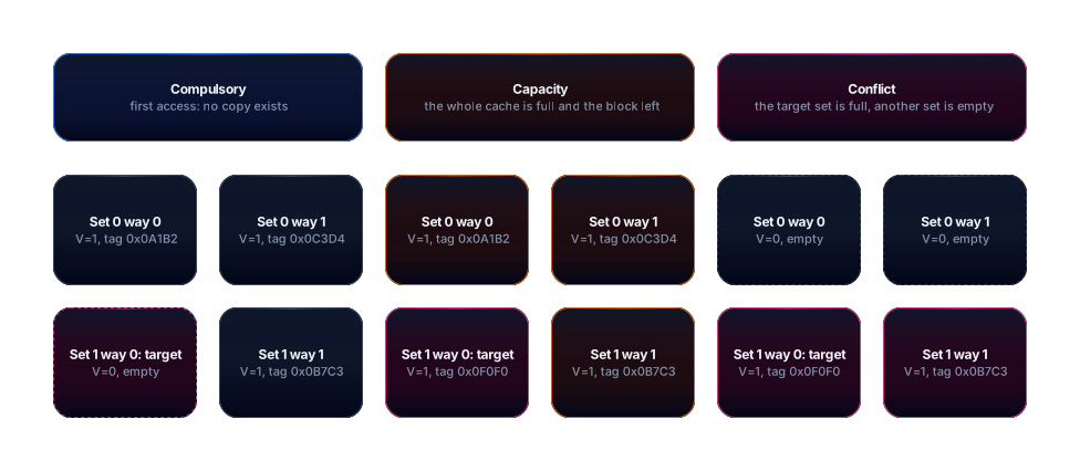
The three cases differ by what surrounds the target. In the compulsory case, the line never existed. In the capacity case, every set is full. In the conflict case, the target’s set is full while set 0 has two empty slots. Associativity only changes the last case, which is why the three are so easy to confuse. An 8-way cache turns many conflicts into hits, but it does not shrink the data set the program needs.
4.6 Replacement policy: LRU and pseudo-LRU
When the set is full and there is a miss, one way has to leave. The most intuitive rule is LRU (least recently used), which evicts the block used longest ago. The idea rests on the temporal locality from lesson 4.1: a block that has not been used for a long time is less likely to be used soon. Exact LRU stores, for each set, the complete order in which the ways were used. The Wikipedia page on replacement policies says that this ordering becomes expensive as associativity grows, which is why it is generally avoided above four ways.
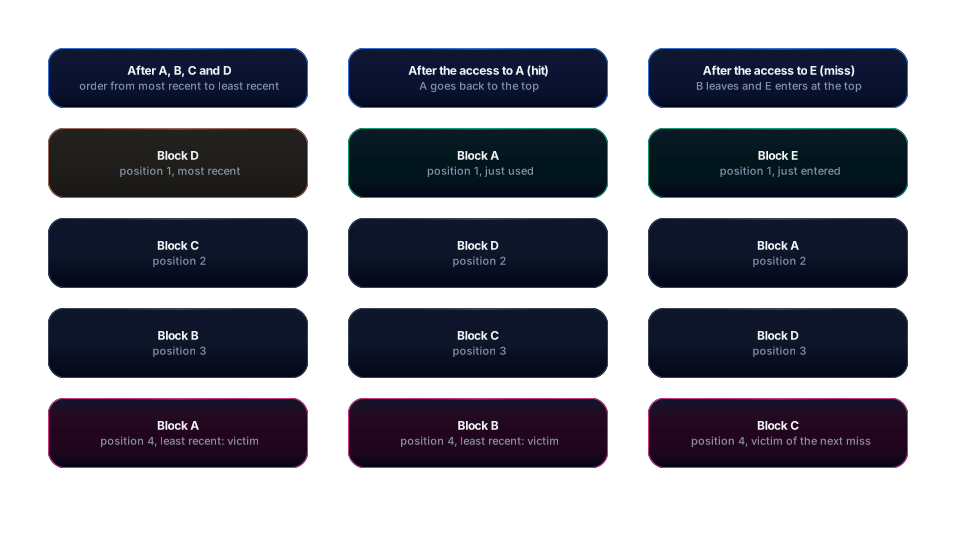
The figure follows the LRU stack of a 4-way set through a sequence of accesses. After A, B, C and D, the order from most recent to least recent is D, C, B, A, and A is the victim. The access to A is a hit, and it moves A to the top. Now the victim is B. When E arrives, there is a miss: B leaves and E enters at the top.
Since exact LRU is expensive, most designs use an approximation. Tree pseudo-LRU uses a binary tree of bits with one bit per internal node. Each bit points to the least recently used side of its node. An access steers the bits along its own path away from the way accessed. To choose the victim, follow the bits from the root to a leaf. A tree with N ways has N minus 1 internal nodes, so there are 3 bits for 4 ways and 7 bits for 8 ways. That count comes from the structure of the tree, not from a specific source.
The figure uses the access sequence 0, 1, 2, 3 and 0 on 4 ways. The final bits are b0 equal to 1 at the root, b1 equal to 1 at the left node, and b2 equal to 0 at the right node.
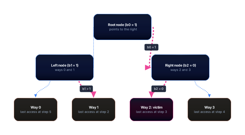
The calculation, done step by step, follows this convention: bit 0 points to the left child, bit 1 points to the right child, and an access steers the bits on its path to the side opposite the accessed one. We start with all bits at 0. The access to way 0 sets the root to 1 (away from the left) and the left node to 1 (away from way 0). The access to way 1 keeps the root at 1 and sets the left node to 0 (away from way 1). The access to way 2 sets the root to 0 (away from the right) and the right node to 1 (away from way 2). The access to way 3 sets the root to 0 again and the right node to 0 (away from way 3). The last access, to way 0, leaves the root at 1 and the left node at 1. The final bits are root 1, left 1 and right 0.
To choose the victim, we follow the bits. The root is 1, so the search goes to the right half. The right node is 0, so the victim is way 2. Exact LRU would choose way 1, which was last used at step 2, while way 2 was used at step 3. The tree does not keep the full order, only which half is older and which way is the oldest inside each half. It is an approximation, and it errs on purpose to save bits and logic.
The Wikipedia page describes PLRU as a choice that uses just one bit per item in the cache, with a miss rate slightly worse than LRU, a slightly lower latency and a smaller hardware cost. That is the trade-off the example shows. Some architectures use random replacement, which keeps no history at all. The same page mentions the use of this method in ARM processors.
4.7 Writes: write-through and write-back
Reading is simple, because the copy in the cache is just a copy. Writing requires a decision, because there are now two versions of the data: the one in the cache and the one in RAM. The write policy defines when RAM learns about the change.
In write-through, every write to the cache is also sent to the level below. RAM is always up to date, and no line needs an extra bit. In write-back, the write stays only in the cache. The line gets the D bit set to 1, and RAM only receives the whole line when it is evicted. The Wikipedia page sums up the difference: in write-through, every write to the cache causes a write to main memory, while in write-back, writes do not go to memory immediately, and the changed locations are marked as dirty.
Each one has its strengths. Write-through is simpler and keeps RAM always equal to the cache, which helps other agents that read memory. Write-back uses fewer transfers when the same line receives many writes, but it needs the D bit and an eviction path, and the eviction can happen long after the original write.
The figure shows three 4-byte stores to the same line, under the two policies.
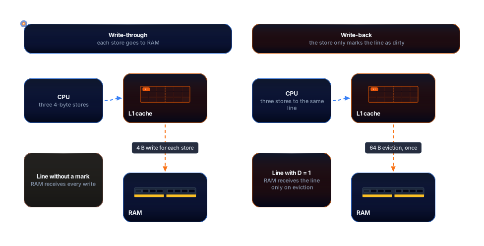
With write-through, each store becomes a 4-byte write to RAM, and the three writes show up as three transfers. With write-back, the three stores only change the L1 line and leave D equal to 1. When the line leaves, RAM receives 64 bytes at once. With three writes, the difference is small, and exercise 4 in section 8 shows the point where the arithmetic flips.
There is also the choice of what to do on a write miss: bring the line into the cache before writing, which is called write-allocate, or write straight to RAM without bringing it in. That part was not read in this check’s sources and is recorded under “What was not confirmed”.
5. Details and edge cases
Associativity has a cost. Each extra way is one more comparator on every access, which uses energy and area, and it can lengthen the hit path. For that reason, there is a point where adding ways stops paying off. The calculation below shows the trade-off with the average memory access time model (AMAT), with 4 cycles of hit time and 14 cycles of miss penalty, which are the L1 and L2 numbers of this reference:
AMAT = hit time + miss rate × miss penalty
In the direct-mapped organization from section 7, the miss rate for the 4 KB stride pattern is 30%. The calculation is 4 + 0.30 × 14 = 8.2 cycles. In the 8-way organization, the same sequence has a rate of 100%, and the calculation is 4 + 1.00 × 14 = 18 cycles. The example assumes the hit time is the same in both organizations, which is usually not true, because an 8-way cache has a wider comparison. That number was not measured in this lesson and appears under “What was not confirmed”. The example is extreme on purpose. It shows what happens when the access pattern falls into the worst case for the organization.
Figure 10 shows why this 4 KB pattern is so bad for 8 ways.
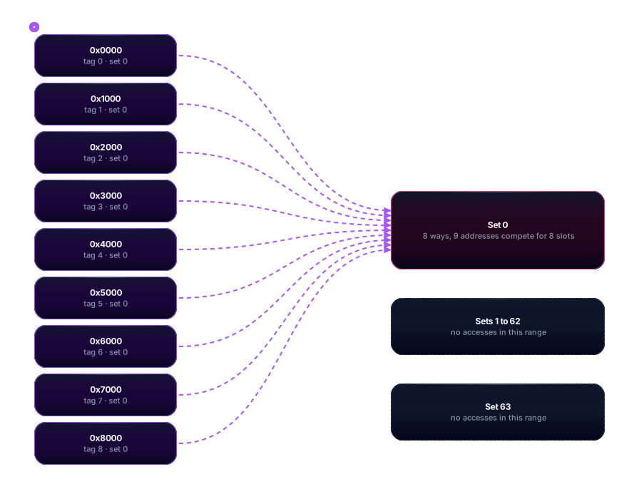
With 64 sets, the index is the bits from 6 to 11. A 4096-byte stride is 2 to the power of 12, so only bit 12 and above change, and the index of every address stays 0. The nine addresses all fall into set 0 and compete for 8 ways. With LRU, cycling through nine blocks in a set of 8 ways makes every access a miss, because the block that leaves is exactly the one that will be read next. This is the typical case where LRU fails: the result depends on the access pattern, not only on the number of ways.
The same capacity, with a different organization, changes the result. In the direct-mapped cache there are 512 sets, and the index uses bits 6 to 14. The 4 KB stride addresses still repeat every 8 steps, so only blocks 0 and 8 land in the same place. That is why the direct organization misses less than the 8-way one in this pattern, and section 7 shows the numbers. Higher associativity is better when conflicts are the problem, but the program’s pattern decides whether they exist.
Spatial locality is the property that associativity affects least. In the 64 KB scan from section 7, the miss rate is 6.25% in all four organizations, because there are no conflicts to solve, only capacity and compulsory misses. Figure 11 shows the two rates side by side.
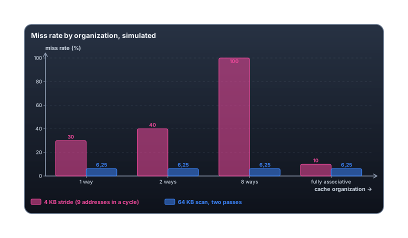
The practical conclusion is that associativity protects temporal locality from conflicts, but no organization protects a pattern that does not fit in the cache. The simulation uses exact LRU, and a processor with pseudo-LRU can miss in a different way. This lesson did not measure any real processor with this pattern.
A few edge points deserve a mention, even without going deep. The L2 and L3 levels also have lines, ways and policies, and the rules in this lesson apply to them with different numbers. The inclusion relationship between the levels is covered in lesson 4.1. In practice, L1 can be indexed with a virtual address, so it does not wait for address translation, and that changes which bits go into the index. This lesson uses physical addresses to keep things simple, and the topic was not explored in depth.
6. Common mistakes and good practices
Mistake 1: thinking the cache stores only what was requested. One requested byte brings a whole 64-byte line, and whoever accesses one byte at a time from scattered data pays for the whole line and uses only a fraction of it. It is like asking for one egg and getting the carton, which also has a price. Good practice: arrange the data that is read together in contiguous areas, so that each line brought in gets used.
Mistake 2: thinking more ways is always better. Section 5 shows the opposite for the 4 KB stride pattern, where the direct organization causes fewer misses than the 8-way one. More ways cost comparators and hit time, and the gain depends on the pattern. Good practice: measure with the program’s real pattern before choosing an organization, and do not rely on the intuition that more means better.
Mistake 3: laying out matrices and vectors with power-of-two strides. A 4 KB or 16 KB stride always falls into the same set, as section 5 shows, and the 4096-by-4096 matrix from lesson 4.1 suffers exactly this when traversed by column. Good practice: if the row size leaves some slack, the model’s own arithmetic shows the effect. With a row of 4096 integers plus 16 integers of padding, each row takes 4160 bytes, and 4160 divided by 64 is 65, so the index advances by 1 on each row and the sets are spread out. This arithmetic belongs to the model and was not measured in this text.
Mistake 4: treating a miss as a defect. A miss is the cache doing its part, which is bringing in the right block when it is not there yet. The real problem is an unnecessary miss, or an expensive one, with a dirty victim and an eviction queue. Good practice: tell apart the three types from section 4.5 before deciding what to change. A compulsory miss calls for a different algorithm, and a conflict miss calls for a different way of accessing the data.
Mistake 5: forgetting the cost of eviction on writes. A write-back cache looks cheap because the writes disappear inside the cache, but the dirty line still leaves someday, and it leaves whole. A program that writes in a scattered way, touching a different line on each write, can cause far more evictions than a program that writes sequentially. Good practice: group the writes that land on the same line, instead of spreading them out.
Mistake 6: assuming 64 bytes on every machine. Section 4.2 showed that the Apple M1 Max used in this lesson has 128-byte lines, and that the same code can behave differently on those machines. Good practice: check the line size of the machine where the code will run, and do not assume a universal value. On macOS, sysctl reports it, as section 7 shows.
7. Simulation and measurement
This section does not measure hardware. It runs a cache simulator with exact LRU, following the rules of section 4, over two access patterns, and counts hits and misses by type. The simulator is deterministic, so the result repeats on any machine with Python 3. The model does not represent pseudo-LRU, prefetching or the real L1 of any processor, and the numbers only hold for the model.
The simulator is below. It was run without changes. Its variable names, comments and output columns are still in Portuguese, so the output matches what the script prints.
"""cache_sim.py: simula uma cache com LRU e conta hits e misses por tipo.

Não mede hardware. Simula a organização (conjuntos, vias, linha) sobre uma
sequência de endereços, para comparar configurações com a mesma capacidade.

Classificação dos misses (modelo dos 3 Cs):
  compulsório: primeira vez que a linha aparece no trace
  capacidade:  a cache totalmente associativa, com a mesma capacidade, também erra
  conflito:    a totalmente associativa acerta, mas a cache real erra

Uso: python3 cache_sim.py
"""
from collections import OrderedDict

LINHA = 64            # bytes por linha
CAPACIDADE = 32 * 1024  # 32 KB
LINHAS = CAPACIDADE // LINHA  # 512 linhas


def simular(trace, vias):
    conjuntos = LINHAS // vias
    cache = [OrderedDict() for _ in range(conjuntos)]  # tag -> True, mais antigo primeiro
    ref = OrderedDict()                                 # referência totalmente associativa
    vistos = set()
    hits = comp = cap = conf = 0
    for end in trace:
        bloco = end // LINHA
        idx = bloco % conjuntos
        tag = bloco // conjuntos
        ref_acerto = bloco in ref
        if ref_acerto:
            ref.move_to_end(bloco)
        else:
            if len(ref) >= LINHAS:
                ref.popitem(last=False)
            ref[bloco] = True
        conj = cache[idx]
        if tag in conj:
            conj.move_to_end(tag)  # LRU: o acerto vira o mais recente
            hits += 1
        else:
            if bloco not in vistos:
                comp += 1
            elif not ref_acerto:
                cap += 1
            else:
                conf += 1
            if len(conj) >= vias:
                conj.popitem(last=False)  # remove o menos recentemente usado
            conj[tag] = True
        vistos.add(bloco)
    total = len(trace)
    return {"acessos": total, "hits": hits, "misses": total - hits,
            "compulsorio": comp, "capacidade": cap, "conflito": conf,
            "taxa_miss": (total - hits) / total}


def trace_passo_4kb(passadas=10):
    # 9 endereços separados por 4 KB, percorridos em ciclo
    base = [k * 4096 for k in range(9)]
    return base * passadas


def trace_varredura(tamanho=64 * 1024, passadas=2):
    # vetor de int de 4 bytes lido em ordem, duas vezes
    seq = [i * 4 for i in range(tamanho // 4)]
    return seq * passadas


CONFIGS = [("direto (1 via)", 1), ("2 vias", 2), ("8 vias", 8), ("totalmente (512 vias)", 512)]

if __name__ == "__main__":
    for nome, trace in [("A) passo de 4 KB, 9 endereços em ciclo, 10 passadas", trace_passo_4kb()),
                        ("B) varredura de 64 KB em ordem, 2 passadas", trace_varredura())]:
        print(nome)
        print(f"{'configuração':<24}{'conjuntos':>10}{'acessos':>9}{'misses':>8}{'taxa':>9}"
              f"{'comp.':>7}{'cap.':>7}{'conf.':>7}")
        for rotulo, vias in CONFIGS:
            r = simular(trace, vias)
            print(f"{rotulo:<24}{LINHAS // vias:>10}{r['acessos']:>9}{r['misses']:>8}"
                  f"{r['taxa_miss'] * 100:>8.2f}%{r['compulsorio']:>7}{r['capacidade']:>7}{r['conflito']:>7}")
        print()
The command used was this one, and the output came out unedited.
python3 cache_sim.pyA) passo de 4 KB, 9 endereços em ciclo, 10 passadas
configuração conjuntos acessos misses taxa comp. cap. conf.
direto (1 via) 512 90 27 30.00% 9 0 18
2 vias 256 90 36 40.00% 9 0 27
8 vias 64 90 90 100.00% 9 0 81
totalmente (512 vias) 1 90 9 10.00% 9 0 0
B) varredura de 64 KB em ordem, 2 passadas
configuração conjuntos acessos misses taxa comp. cap. conf.
direto (1 via) 512 32768 2048 6.25% 1024 1024 0
2 vias 256 32768 2048 6.25% 1024 1024 0
8 vias 64 32768 2048 6.25% 1024 1024 0
totalmente (512 vias) 1 32768 2048 6.25% 1024 1024 0The numbers match the arithmetic of the structure. In pattern A, the direct organization has 512 sets, and the blocks with index 0 and 8 fall into the same set. Blocks 0 and 8 compete for one way and miss on every pass after the first. The arithmetic is 9 compulsory misses, plus 2 per pass over 9 passes, which gives 9 plus 18, or 27 misses. In the 2-way organization, blocks 0, 4 and 8 fall into the same set of 256, and that is 3 blocks for 2 ways: 9 plus 3 times 9, or 36 misses. In the 8-way one, the 9 blocks fall into the same set of 8 ways: 9 plus 9 times 9, or 90 misses. The fully associative cache has 512 ways, and the 9 blocks fit, so there are only the 9 compulsory misses.
In pattern B, the vector has 16384 four-byte integers, or 2048 lines. Each pass causes 1024 misses, because 2048 lines do not fit into 512 entries, and the second pass finds the lines already evicted. That gives 2048 misses in 32768 accesses, or 6.25%, in every organization. The 1024 compulsory misses come from the first pass, and the 1024 capacity misses come from the second. There are no conflicts, because the pattern is sequential.
The machine used in this lesson was queried with the command below. It shows the geometry that section 4.2 uses for the Apple M1 Max.
sysctl hw.perflevel0.l1icachesize hw.perflevel0.l1dcachesize hw.perflevel0.l2cachesize hw.perflevel1.l1dcachesize hw.perflevel1.l2cachesize hw.cachelinesize hw.cachesizehw.perflevel0.l1icachesize: 196608
hw.perflevel0.l1dcachesize: 131072
hw.perflevel0.l2cachesize: 12582912
hw.perflevel1.l1dcachesize: 65536
hw.perflevel1.l2cachesize: 4194304
hw.cachelinesize: 128
hw.cachesize: 3370532864 65536 4194304 0 0 0 0 0 0 0The sysctl confirms the line size, which is 128 bytes, and the cache sizes of the two core types: 128 KB of data L1 and 12 MB of L2 on the performance core, and 64 KB of data L1 and 4 MB of L2 on the efficiency core. It does not report associativity, so that number is left out of the arithmetic.
8. Exercises
Practice with the questions below. The solutions come right after, with the arithmetic done by hand.
Question 1
In the 32 KB L1, with 8 ways and 64-byte lines, calculate the tag, index and offset of address 0xBEEF. Remember that 0xBEEF is 48879 in decimal.
Question 2
A 256 KB cache, with 4 ways and 128-byte lines, serves a processor with 32-bit addresses. How many bits does each field have: tag, index and offset?
Question 3
A 4-way set receives, in this order, accesses to A, B, C, D, A and E. Which block leaves the cache under exact LRU? Then redo the calculation for the pseudo-LRU tree with the access sequence 0, 1, 2, 3 (without the last access to way 0). Which way does the tree choose?
Question 4
A loop writes 10 times into 4 bytes of the same line, and the line leaves the cache afterwards. Compare the number of bytes transferred with write-through and with write-back, in this lesson’s simple model. Then find out from how many writes to the same line write-back starts to transfer fewer bytes.
Solutions
Solution to question 1
The offset is the 6 lowest bits. Since 0xBEEF is 48879, and 48879 divided by 64 gives 763 with remainder 47, the offset is 47. That is the remainder of the division, which matches the 6 low bits of the address.
The index is the next 6 bits, which are the quotient 763 with the 6-bit mask applied. We have 763 modulo 64, which gives 59. So the index is 59, and the address looks in set 59.
The tag is the bits left over, that is, the address divided by 4096, which is 48879 divided by 4096, with quotient 11. In hexadecimal, 11 is 0xB. So the tag is 0xB.
In short: tag 0xB, index 59 and offset 47.
Solution to question 2
First, the number of lines: 256 KB divided by 128 bytes gives 2048 lines. Then, the number of sets: 2048 divided by 4 ways gives 512 sets.
The index needs 9 bits, because 2 to the power of 9 is 512. The offset needs 7 bits, because 2 to the power of 7 is 128. The tag takes the rest: 32 minus 9 minus 7, which gives 16 bits.
Solution to question 3
With exact LRU, the order after A, B, C and D is D, C, B, A, so A is the victim. The access to A is a hit, and the order becomes A, D, C, B, with B as the victim. The miss on E evicts B. The answer is B.
With pseudo-LRU, follow the convention in section 4.6. After accesses 0, 1, 2 and 3, the root is 0, because the last access went right, and the left node is 0, because the access to way 1 left it pointing to way 0. The calculation goes like this: the access to way 0 sets the root to 1 and the left node to 1; the access to way 1 sets the left node to 0; the access to way 2 sets the root to 0 and the right node to 1; the access to way 3 sets the right node to 0. With the root at 0, the search goes left, and the left node at 0 points to way 0. The tree chooses way 0. Exact LRU would also choose way 0, because it was used for the first time at step 1 and never again. In this case, the approximation gets it right.
Solution to question 4
With write-through, each of the 10 writes of 4 bytes goes to RAM, which gives 10 times 4, or 40 bytes transferred.
With write-back, the 10 writes stay in the cache, and the dirty line leaves once, with 64 bytes. The total is 64 bytes.
In this case, write-through transfers fewer bytes. The turning point comes when the number of writes, n, makes 4 times n equal 64. So n is 16. From 17 writes to the same line onward, write-back transfers fewer bytes. This is a simple model, in which all writes have the same size, the line leaves only once, and there are no reads in between. With write-through combined into buffers, the arithmetic changes, and that was not measured in this lesson.
9. Glossary
Tag: the upper part of the address, stored in each line to say which block it contains.
Index: the address field that picks the set where the block may be.
Offset: the field of the least significant bits of the address, which picks the byte inside the line.
Cache line: the unit of transfer between RAM and the cache. It has 64 bytes in this lesson’s reference.
Set: a group of lines that share the same index.
Way: the position of a line inside a set. A set with N ways has N possible positions for a block.
V bit (valid): indicates whether the entry holds valid data.
D bit (dirty): indicates that the line was changed since it came from RAM, and must be written when it leaves (write-back).
Hit: an access in which the data is in the level consulted.
Miss: an access in which the data is not in the level consulted, and must come from the level below.
Compulsory miss: the first access to a block, when no copy exists.
Capacity miss: a miss that would also happen in a fully associative cache of the same size.
Conflict miss: a miss that would not happen in a fully associative cache of the same size, caused by a full set.
Victim: the line chosen to leave when a full set has to receive a new block.
LRU (least recently used): a policy that evicts the block used longest ago.
PLRU (pseudo-LRU): an approximation of LRU with bits in a tree, used to save hardware.
Write-through: a policy in which each write to the cache also goes to the level below.
Write-back: a policy in which the write stays in the cache, and the dirty line is only written on eviction.
Write-allocate: a policy in which a write miss brings the line into the cache before writing.
Associativity: the number of ways per set. With 1 way, the organization is direct mapped; with all lines in one set, it is fully associative.
Stride: the distance between two successive accesses to a vector or matrix.
AMAT (average memory access time): the hit time plus the miss rate times the miss penalty.
What was not confirmed
This section lists what the lesson states without a primary source or its own measurement.
The geometry of the Zen 4 data L1 (32 KB, 8 ways, 64-byte lines and write-back) comes from WikiChip and a search summary from Chips and Cheese. AMD’s optimization guide, document 56665, was not opened in this check.
The associativity of the Apple M1 Max L1 was not checked. sysctl confirms the line size and the L1 size, but not the number of ways.
The 128-byte lines of POWER7 to POWER9 come from WikiChip and the LLVM discussion, cited in lesson 4.1. They were not read in the IBM manual.
The 8-way hit time in the example in section 5 is an assumption that it equals the direct-mapped one. That hit time was not measured.
The AMAT example uses a 14-cycle L2 penalty, with this track’s reference. It is a model, not a measurement of a real miss, which also depends on dirty victims.
The 30% miss rate for the direct organization and 100% for 8 ways, in the 4 KB stride pattern, comes from the simulator with exact LRU. It is not a hardware measurement. A processor with pseudo-LRU may give another number.
Write-allocate, the write-miss policy, was not read in this check’s sources. The Wikipedia page consulted was cut off before that part. The description in this lesson is conceptual.
The three Cs taxonomy is attributed to Mark Hill and to Hill and Smith, in works from 1987 and 1989. Those works were not read in this check, and the attribution comes from the bibliography cited below, without direct verification.
The lesson did not verify which pseudo-LRU tree each real processor uses. The example in section 4.6 follows a tree convention of its own, which illustrates the mechanism.
Whether L1 is indexed by virtual or physical address, the number of physical address bits of each processor, and the inclusion relationship between levels were not confirmed for the machines mentioned. The 48-bit address in section 4.1 is just an example calculation.
The effect of the 4160-byte padding in section 6 is a model calculation and was not measured.
No real hardware latency or miss rate was measured in this lesson. The L1, L2 and L3 latency numbers come from lesson 4.1, and they come from a reference CPU converted to 4.0 GHz, as that lesson explains.
Sources
Consulted on November 2, 2026.
- Wikipedia (English). “Cache replacement policies”. LRU with growing cost, “generally > four ways”; PLRU with one bit per item and a pointer tree; random replacement and its use in ARM processors. Available at: https://en.wikipedia.org/wiki/Cache_replacement_policies
- Wikipedia (English). “CPU cache”. Write-through and write-back, dirty bit, direct mapped, associative and fully associative organizations, splitting the address into tag, index and offset. Partial reading, up to about 100 thousand of the page’s 178 thousand characters. Available at: https://en.wikipedia.org/wiki/CPU_cache
- WikiChip. “Zen 4”, with a 32 KiB data L1, 8 ways, 64-byte lines and write-back. Read from the search summary. Available at: https://en.wikichip.org/wiki/zen_4
- Chips and Cheese. “Details on the Gigabyte Leak”, with a 32 KB data L1 and 8 ways for Zen 3 and Zen 4. Read from the search summary. Available at: https://chipsandcheese.com/p/details-on-the-gigabyte-leak
- Chips and Cheese. “AMD’s Mild Hybrid Strategy: Ryzen Z1 in ASUS’s ROG Ally”, February 12, 2024. L1, L2, L3 and main memory latencies reused from lesson 4.1. Available at: https://chipsandcheese.com/p/amds-mild-hybrid-strategy-ryzen-z1-in-asuss-rog-ally
- Local measurement: sysctl on a MacBook Pro with Apple M1 Max, macOS 27.0.1, run on November 2, 2026. The output is in section 7.
- Bibliography cited without being read in this check: HENNESSY, John L.; PATTERSON, David A. Computer Architecture: A Quantitative Approach. 6th ed. Cambridge: Morgan Kaufmann, 2017. Chapter on memory hierarchy. HILL, Mark D.; SMITH, Alan J. “Evaluating Associativity in CPU Caches”. IEEE Transactions on Computers, 1989.
Related
- Hardware track
- Memory hierarchy and locality
- SRAM, DRAM and storage
- Pipeline, cache and parallelism
- ALU and registers
- Lesson 4.4, Addressing, alignment and endianness, not written yet.